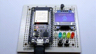
ESP32 Demo Board
ESP32 Training Board
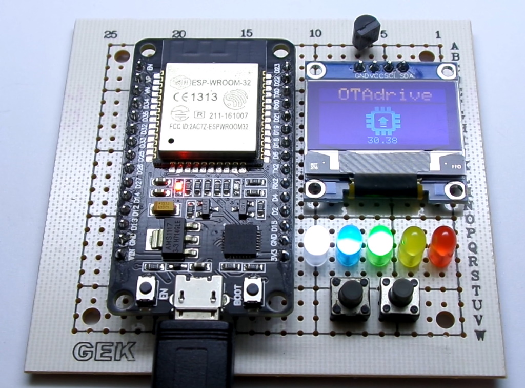
We are going to make a simple demo kit for our tutorials, this board let us do more practical examples. The board contains two tact switches, one DS18B20 temperature sensor, an OLED display, and 5 LEDs. We want to make the board with simple parts that everyone could access.
Schematic and components
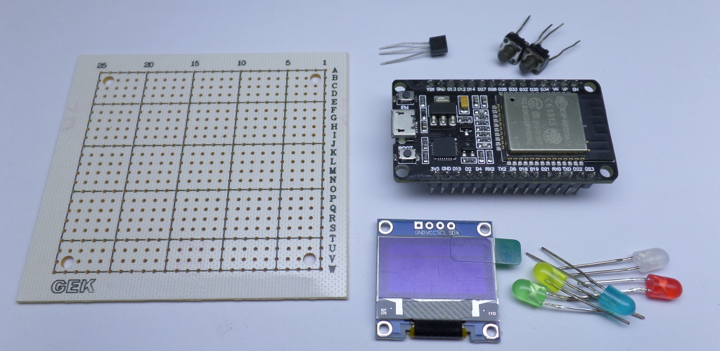
The following image shows the main parts we have used in this board.
 {.mud-image .fluid .object-fill .object-center}
The board contains the following parts |Qty|Component |-|- 1|ESP32 Devkit (30 pin) 1|0.96 inch I2C OLED 1|DS18B20 2|Tact switch 5|Colored LED
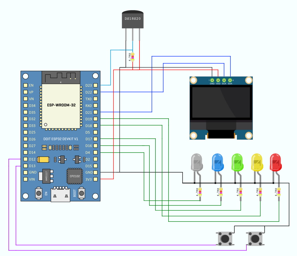
The following schematic diagram shows the wiring of the components.
 {.mud-image .fluid .object-fill .object-center}
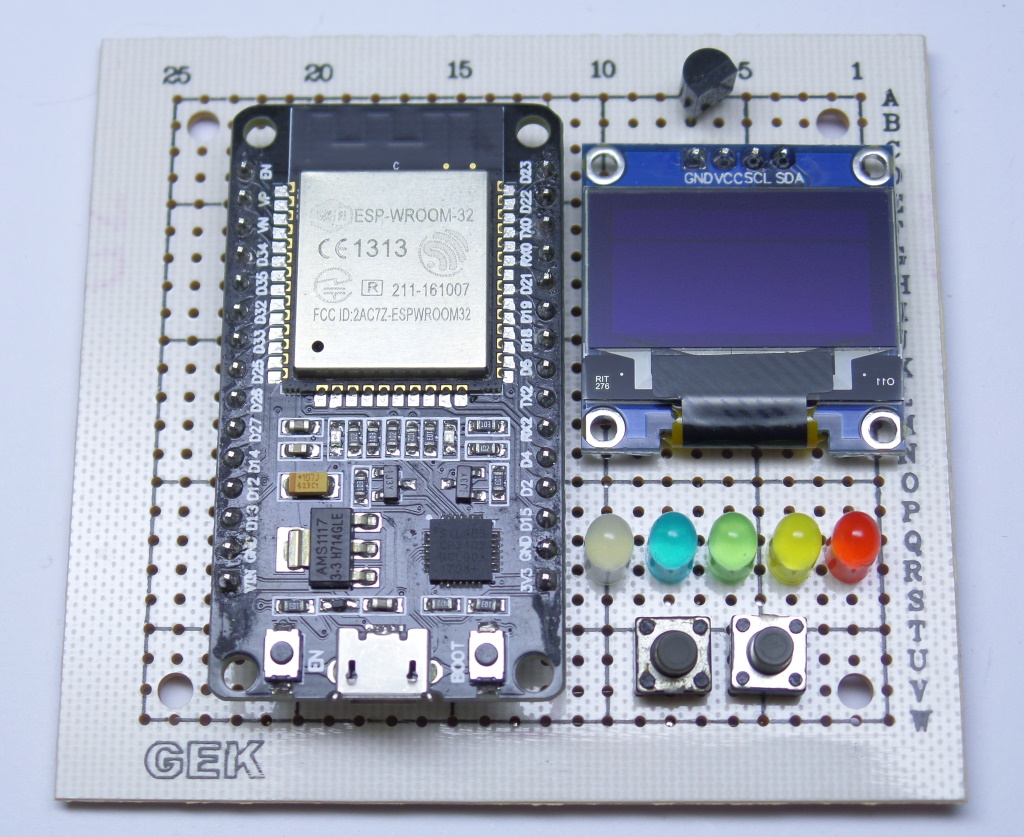
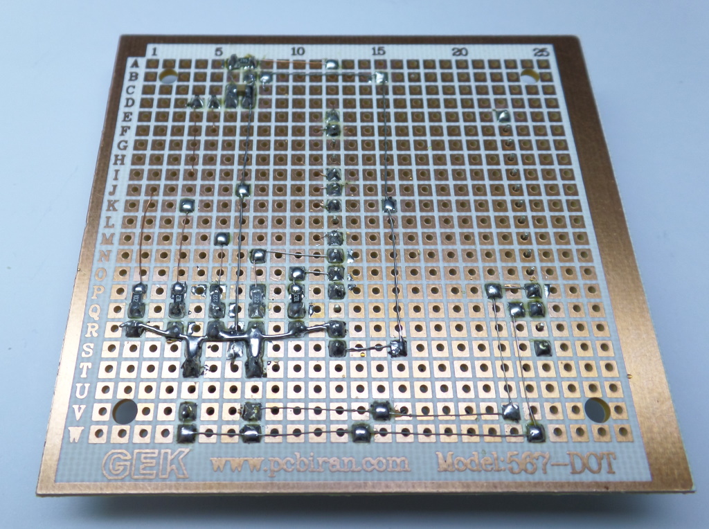
Assembly
Here we made it.
 {.mud-image .fluid .object-fill .object-center}
 {.mud-image .fluid .object-fill .object-center}
{.mud-image .fluid .object-fill .object-center}
Test It
The following code could test all components on the board. You can find complete source code on our github repository.
 {.mud-image .fluid .object-fill .object-center}
#include <SPI.h>
#include <Wire.h>
#include <Adafruit_GFX.h>
#include <Adafruit_SSD1306.h>
#include <otadrive_esp.h>

#include "OneWireNg_CurrentPlatform.h"
#include "drivers/DSTherm.h"
#include "utils/Placeholder.h"

#define LED_W 4
#define LED_B 16
#define LED_G 17
#define LED_Y 18
#define LED_R 19
#define BTN1 13
#define BTN2 12
#define OW 23

#define SCREEN_ADDRESS 0x3C
Adafruit_SSD1306 display(128, 64, &Wire, -1);

static Placeholder<OneWireNg_CurrentPlatform> _ow;

// 'logo128', 34x34px
const unsigned char epd_bitmap_logo128[] PROGMEM = {
    0x00, 0x79, 0xe7, 0x80, 0x00, 0x00, 0x79, 0xe7, 0x80, 0x00, 0x00, 0x79, 0xe7, 0x80, 0x00, 0x00,
    0x79, 0xe7, 0x80, 0x00, 0x00, 0x79, 0xe7, 0x80, 0x00, 0x03, 0xff, 0xff, 0xf0, 0x00, 0x07, 0xff,
    0xff, 0xf8, 0x00, 0x07, 0xff, 0xff, 0xf8, 0x00, 0x07, 0x80, 0x00, 0x78, 0x00, 0xff, 0x00, 0x00,
    0x3f, 0xc0, 0xff, 0x00, 0x00, 0x3f, 0xc0, 0xff, 0x00, 0x00, 0x3f, 0xc0, 0xff, 0x00, 0xc0, 0x3f,
    0xc0, 0x07, 0x01, 0xe0, 0x38, 0x00, 0x07, 0x03, 0xf0, 0x38, 0x00, 0xff, 0x07, 0xf8, 0x3f, 0xc0,
    0xff, 0x0f, 0xfc, 0x3f, 0xc0, 0xff, 0x03, 0xf0, 0x3f, 0xc0, 0xff, 0x03, 0xf0, 0x3f, 0xc0, 0x07,
    0x03, 0xf0, 0x38, 0x00, 0x07, 0x00, 0x00, 0x38, 0x00, 0xff, 0x03, 0xf0, 0x3f, 0xc0, 0xff, 0x00,
    0x00, 0x3f, 0xc0, 0xff, 0x03, 0xf0, 0x3f, 0xc0, 0xff, 0x00, 0x00, 0x3f, 0xc0, 0x07, 0x80, 0x00,
    0x78, 0x00, 0x07, 0xff, 0xff, 0xf8, 0x00, 0x07, 0xff, 0xff, 0xf8, 0x00, 0x03, 0xff, 0xff, 0xf0,
    0x00, 0x00, 0x79, 0xe7, 0x80, 0x00, 0x00, 0x79, 0xe7, 0x80, 0x00, 0x00, 0x79, 0xe7, 0x80, 0x00,
    0x00, 0x79, 0xe7, 0x80, 0x00, 0x00, 0x79, 0xe7, 0x80, 0x00};

const int leds[] = {LED_W, LED_B, LED_G, LED_Y, LED_R};

float readD18B20()
{
  OneWireNg::Id id;
  DSTherm drv(_ow);
  Placeholder<DSTherm::Scratchpad> _scrpd;
  drv.convertTempAll(DSTherm::SCAN_BUS, false);

  for (const auto &id : (OneWireNg &)_ow)
  {
    if (drv.readScratchpad(id, &_scrpd) == OneWireNg::EC_SUCCESS)
    {
      return ((float)((DSTherm::Scratchpad)_scrpd).getTemp()) / 1000.0f;
    }
  }
  return NAN;
}

void setup()
{
  if (!display.begin(SSD1306_SWITCHCAPVCC, SCREEN_ADDRESS))
  {
    Serial.println(F("SSD1306 allocation failed"));
    for (;;)
      ; // Don't proceed, loop forever
  }

  for (int i = 0; i < 5; i++)
    pinMode(leds[i], OUTPUT);

  display.clearDisplay();
  display.setTextColor(WHITE, BLACK);
  display.setTextSize(2);
  display.setCursor(20, 0);
  display.print("OTAdrive");
  display.drawBitmap(47, 20, epd_bitmap_logo128, 34, 34, WHITE);

  // Show the display buffer on the screen. You MUST call display() after
  // drawing commands to make them visible on screen!
  display.display();

  new (&_ow) OneWireNg_CurrentPlatform(OW, false);
}

void loop()
{
  for (int i = 0; i < 5; i++)
  {
    digitalWrite(leds[i], 1);
    delay(200);
  }

  for (int i = 0; i < 5; i++)
  {
    digitalWrite(leds[i], 0);
    delay(200);
  }

  display.setTextSize(1);
  display.setCursor(48, 56);
  display.printf("%4.2f", readD18B20());
  display.display();
}